
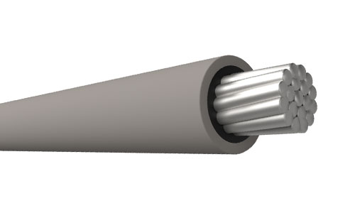
Covered Conductors Type CC & Type CCT – AS/NZS 3675
covered conductor, CC covered conductor, CCT covered conductor, AS/NZS 3675, covered overhead conductor, XLPE covered conductor, 11kV covered conductor, 22kV covered conductor, 33kV covered conductor, spacer cable conductor, overhead distribution conductor
- AS/NZS 3675 Medium Voltage Overhead Conductors
- 6.35/11 kV – 19/33 kV Applications
- Water-Blocked Aluminium Alloy Conductor
- Track-Resistant UV-Stabilised XLPE Covering
- Custom Specifications | Direct Factory Supply | MOQ: 10KM
Product Overview
QZ Cable manufactures Covered Conductors Type CC and Type CCT designed in accordance with the AS/NZS 3675 standard.
These covered overhead conductors feature an insulating covering without conductor screens or insulation screens. They are designed to operate under principles similar to bare overhead conductor systems, with additional covering to improve protection against intermittent contact, environmental exposure and certain overhead line faults.
The product range includes two main types: CC Covered Conductors and CCT Covered Conductors. Both types are available with different conductor materials and covering constructions to suit specific overhead distribution network requirements.
Applications
AS/NZS 3675 covered conductors are used in overhead power distribution networks, particularly where additional protection against environmental and external contact risks is required.
Typical applications include:
- Overhead power distribution networks from 11 kV to 33 kV, subject to the applicable conductor type and system design.
- Overhead lines installed in areas with trees and vegetation.
- Distribution networks exposed to polluted environments.
- Compact overhead line arrangements and spacer cable systems.
- Insulated Unscreened Conductor (IUC) systems, where applicable.
- Installations requiring additional protection against intermittent contact between phases or between a conductor and ground.
Covered Conductor Classification
There are two main types of covered conductors under this product range:
- CC – Covered Conductor
- CCT – Covered Conductor with Full-Thickness Covering
1. CC Covered Conductors
CC covered conductors have a covering with a minimum average thickness of 2.0 mm and are designed for use at working voltages up to and including 19/33 kV.
They can withstand intermittent contact with conductive materials between phases or between a phase conductor and ground, such as tree branches. However, they should not remain in permanent contact with these materials.
Construction
- Conductor: Aluminium, aluminium alloy or aluminium-clad steel.
- Water Blocking: Special water-blocking material meeting the applicable AS/NZS 3675 test requirements.
- Covering: Track-resistant, UV-stabilised XLPE.
- Marking: The external surface is marked with “CC”, manufacturer logo, year of manufacture and conductor material. Sequential six-digit numbers are printed at 1-metre intervals, with the lowest number at the inner end of the drum.
2. CCT Covered Conductors – Full-Thickness Covering
CCT covered conductors have a specified covering thickness for each nominated working voltage.
They operate under principles similar to bare conductor or CC systems, but have electrical and mechanical characteristics that allow them to remain in contact with tree limbs for extended periods. The actual duration depends on the abrasive characteristics of the tree, prevailing wind frequency and strength, and operating temperature.
CCT conductors also offer improved performance in polluted environments and are suitable for spacer cable systems and Insulated Unscreened Conductor (IUC) systems.
Construction
- Conductor: Aluminium, aluminium alloy or aluminium-clad steel.
- Water Blocking: Special water-blocking material meeting the applicable AS/NZS 3675 test requirements.
- Covering Option 1: Track-resistant, UV-stabilised XLPE.
- Covering Option 2: Inner layer of non-UV-stabilised XLPE and outer layer of UV-stabilised HDPE.
- HDPE Layer Requirements: For the XLPE/HDPE construction, the average HDPE thickness is not more than 40% of the specified minimum average covering thickness and not less than 1.0 mm.
- Marking: The external surface is marked with “CCT”, manufacturer logo, year of manufacture and conductor material. Sequential six-digit numbers are printed at 1-metre intervals, with the lowest number at the inner end of the drum.
Applicable Standards
- AS/NZS 3675:2002 – Conductors – Covered overhead – For working voltages 6.35/11 (12) kV up to and including 19/33 (36) kV.
- AS/NZS 3808 – Insulating and sheathing materials for electric cables, where referenced by the selected covering compound.
- AS 3607 – Conductors – Bare overhead – Aluminium and aluminium alloy, where applicable to the selected conductor material.
The final manufacturing and testing requirements should follow the applicable edition of AS/NZS 3675 and the customer’s approved technical specification.
Why Choose QZ Cable?
- Manufacturer Since 1969: Qingzhou Cable is part of QZ Group, with experience in cable and conductor manufacturing.
- Type CC & CCT Options: Different covering designs to meet project-specific overhead distribution requirements.
- Water-Blocked Construction: Designed to meet the applicable water-blocking requirements.
- UV-Stabilised Covering: XLPE and optional XLPE/HDPE covering systems for outdoor applications.
- Customized Manufacturing: Conductor sizes, covering thicknesses and material configurations according to approved specifications.
- Factory-Direct Supply: Supporting power utilities, EPC contractors, distributors and international bulk buyers.
Contact QZ Cable for technical datasheets, conductor dimensions and quotations for AS/NZS 3675 Type CC and Type CCT covered conductors.
Technical Specifications
1. AS/NZS 3675 – General Covered Conductor Performance
The following technical data covers Alloy 6201 and Alloy 1120 conductors.
| Conductor Alloy | Conductor Size (No./mm) | DC Resistance at 20°C (Ω/km) | AC Resistance at 80°C (Ω/km) | Reactance at 50 Hz (Ω/km) | Current Capacity at 30°C – Still Air (A) | 30°C – 1.0 m/s Wind (A) | 30°C – 2.0 m/s Wind (A) | Current Capacity at 40°C – Still Air (A) | 40°C – 1.0 m/s Wind (A) | 40°C – 2.0 m/s Wind (A) | 1-sec Fault Current (kA) | Everyday Working Tension (kN) | Maximum Working Tension (kN) | Minimum Breaking Load (kN) | Minimum Bending Radius (mm) |
|---|---|---|---|---|---|---|---|---|---|---|---|---|---|---|---|
| Alloy 6201 | 7/2.75 | 0.799 | 0.988 | 0.331 | 125 | 210 | 235 | 110 | 185 | 210 | 3.5 | 1.51 | 5.8 | 11.6 | 200 |
| Alloy 6201 | 7/3.75 | 0.43 | 0.532 | 0.312 | 180 | 300 | 345 | 160 | 270 | 310 | 6.4 | 2.82 | 10.9 | 21.7 | 245 |
| Alloy 6201 | 7/4.75 | 0.268 | 0.331 | 0.297 | 245 | 410 | 465 | 220 | 365 | 415 | 10.3 | 4.52 | 17.4 | 34.8 | 290 |
| Alloy 6201 | 19/3.50 | 0.183 | 0.227 | 0.281 | 315 | 515 | 595 | 280 | 460 | 530 | 15.2 | 6.67 | 25.7 | 51.3 | 340 |
| Alloy 1120 | 7/2.75 | 0.713 | 0.881 | 0.331 | 130 | 220 | 250 | 115 | 195 | 225 | 3.7 | 1.49 | 4.96 | 9.91 | 200 |
| Alloy 1120 | 7/3.75 | 0.383 | 0.474 | 0.312 | 190 | 320 | 365 | 170 | 285 | 325 | 6.8 | 2.64 | 8.8 | 17.6 | 245 |
| Alloy 1120 | 7/4.75 | 0.239 | 0.296 | 0.297 | 260 | 430 | 485 | 230 | 385 | 435 | 11 | 4.07 | 13.6 | 27.1 | 290 |
| Alloy 1120 | 19/3.50 | 0.163 | 0.202 | 0.281 | 330 | 545 | 625 | 295 | 485 | 560 | 16.2 | 6.26 | 20.9 | 41.7 | 340 |
2. CCT Technical Performance – Alloy 6201
11 kV Covered Conductors
| Conductor Size (No./mm) | DC Resistance at 20°C (Ω/km) | AC Resistance at 80°C (Ω/km) | Reactance at 50 Hz (Ω/km) | 30°C Still Air (A) | 30°C 1.0 m/s Wind (A) | 30°C 2.0 m/s Wind (A) | 40°C Still Air (A) | 40°C 1.0 m/s Wind (A) | 40°C 2.0 m/s Wind (A) | Fault Current 1 sec. (kA) | Everyday Working Tension (kN) | Maximum Working Tension (kN) | Minimum Breaking Load (kN) | Minimum Bending Radius (mm) |
|---|---|---|---|---|---|---|---|---|---|---|---|---|---|---|
| 7/3.75 | 0.43 | 0.532 | 0.312 | 185 | 295 | 330 | 165 | 265 | 295 | 6.4 | 2.82 | 10.9 | 21.7 | 285 |
| 7/4.75 | 0.268 | 0.331 | 0.297 | 245 | 390 | 440 | 220 | 350 | 395 | 10.3 | 4.52 | 17.4 | 34.8 | 330 |
| 19/3.50 | 0.183 | 0.227 | 0.281 | 315 | 500 | 560 | 280 | 445 | 500 | 15.2 | 6.67 | 25.7 | 51.3 | 380 |
22 kV Covered Conductors
| Conductor Size (No./mm) | DC Resistance at 20°C (Ω/km) | AC Resistance at 80°C (Ω/km) | Reactance at 50 Hz (Ω/km) | 30°C Still Air (A) | 30°C 1.0 m/s Wind (A) | 30°C 2.0 m/s Wind (A) | 40°C Still Air (A) | 40°C 1.0 m/s Wind (A) | 40°C 2.0 m/s Wind (A) | Fault Current 1 sec. (kA) | Everyday Working Tension (kN) | Maximum Working Tension (kN) | Minimum Breaking Load (kN) | Minimum Bending Radius (mm) |
|---|---|---|---|---|---|---|---|---|---|---|---|---|---|---|
| 7/3.75 | 0.43 | 0.532 | 0.312 | 185 | 285 | 315 | 165 | 255 | 280 | 6.4 | 2.82 | 10.9 | 21.7 | 350 |
| 7/4.75 | 0.268 | 0.331 | 0.297 | 245 | 375 | 420 | 220 | 335 | 375 | 10.3 | 4.52 | 17.4 | 34.8 | 395 |
| 19/3.50 | 0.183 | 0.227 | 0.281 | 315 | 475 | 530 | 280 | 425 | 475 | 15.2 | 6.67 | 25.7 | 51.3 | 445 |
33 kV Covered Conductors
| Conductor Size (No./mm) | DC Resistance at 20°C (Ω/km) | AC Resistance at 80°C (Ω/km) | Reactance at 50 Hz (Ω/km) | 30°C Still Air (A) | 30°C 1.0 m/s Wind (A) | 30°C 2.0 m/s Wind (A) | 40°C Still Air (A) | 40°C 1.0 m/s Wind (A) | 40°C 2.0 m/s Wind (A) | Fault Current 1 sec. (kA) | Everyday Working Tension (kN) | Maximum Working Tension (kN) | Minimum Breaking Load (kN) | Minimum Bending Radius (mm) |
|---|---|---|---|---|---|---|---|---|---|---|---|---|---|---|
| 7/3.75 | 0.43 | 0.532 | 0.312 | 185 | 270 | 295 | 165 | 240 | 265 | 6.4 | 2.82 | 10.9 | 21.7 | 425 |
| 7/4.75 | 0.268 | 0.331 | 0.297 | 245 | 360 | 400 | 220 | 320 | 355 | 10.3 | 4.52 | 17.4 | 34.8 | 470 |
| 19/3.50 | 0.183 | 0.227 | 0.281 | 315 | 455 | 505 | 280 | 405 | 450 | 15.2 | 6.67 | 25.7 | 51.3 | 520 |
3. XLPE Covered Aerial Cables – Alloy 1120 Conductors
The source also provides the following voltage-specific technical data for XLPE covered aerial cables using Alloy 1120 conductors.
11 kV Covered Conductors
| Conductor Size (No./mm) | DC Resistance at 20°C (Ω/km) | AC Resistance at 80°C (Ω/km) | Reactance at 50 Hz (Ω/km) | 30°C Still Air (A) | 30°C 1.0 m/s Wind (A) | 30°C 2.0 m/s Wind (A) | 40°C Still Air (A) | 40°C 1.0 m/s Wind (A) | 40°C 2.0 m/s Wind (A) | Fault Current 1 sec. (kA) | Everyday Working Tension (kN) | Maximum Working Tension (kN) | Minimum Breaking Load (kN) | Minimum Bending Radius (mm) |
|---|---|---|---|---|---|---|---|---|---|---|---|---|---|---|
| 7/2.75 | 0.713 | 0.881 | 0.331 | 130 | 215 | 240 | 115 | 190 | 215 | 3.7 | 1.49 | 4.96 | 9.9 | 230 |
| 7/3.75 | 0.383 | 0.474 | 0.312 | 190 | 315 | 345 | 170 | 280 | 310 | 6.8 | 2.64 | 8.8 | 17.6 | 285 |
| 7/4.75 | 0.239 | 0.296 | 0.297 | 26() | 415 | 470 | 230 | 370 | 420 | 11 | 4.07 | 13.6 | 27.1 | 330 |
| 19/3.50 | 0.163 | 0.202 | 0.281 | 330 | 525 | 595 | 295 | 470 | 530 | 16.2 | 6.26 | 20.9 | 41.7 | 380 |
22 kV Covered Conductors
| Conductor Size (No./mm) | DC Resistance at 20°C (Ω/km) | AC Resistance at 80°C (Ω/km) | Reactance at 50 Hz (Ω/km) | 30°C Still Air (A) | 30°C 1.0 m/s Wind (A) | 30°C 2.0 m/s Wind (A) | 40°C Still Air (A) | 40°C 1.0 m/s Wind (A) | 40°C 2.0 m/s Wind (A) | Fault Current 1 sec. (kA) | Everyday Working Tension (kN) | Maximum Working Tension (kN) | Minimum Breaking Load (kN) | Minimum Bending Radius (mm) |
|---|---|---|---|---|---|---|---|---|---|---|---|---|---|---|
| 7/2.75 | 0.713 | 0.881 | 0.331 | 135 | 205 | 225 | 120 | 185 | 200 | 3.7 | 1.49 | 4.96 | 9.9 | 300 |
| 7/3.75 | 0.383 | 0.474 | 0.312 | 190 | 295 | 330 | 170 | 265 | 295 | 6.8 | 2.64 | 8.8 | 17.6 | 350 |
| 7/4.75 | 0.239 | 0.296 | 0.297 | 260 | 400 | 440 | 230 | 355 | 395 | 11 | 4.07 | 13.6 | 27.1 | 395 |
| 19/3.50 | 0.163 | 0.202 | 0.281 | 330 | 505 | 560 | 295 | 450 | 500 | 16.2 | 6.26 | 20.9 | 41.7 | 445 |
33 kV Covered Conductors
| Conductor Size (No./mm) | DC Resistance at 20°C (Ω/km) | AC Resistance at 80°C (Ω/km) | Reactance at 50 Hz (Ω/km) | 30°C Still Air (A) | 30°C 1.0 m/s Wind (A) | 30°C 2.0 m/s Wind (A) | 40°C Still Air (A) | 40°C 1.0 m/s Wind (A) | 40°C 2.0 m/s Wind (A) | Fault Current 1 sec. (kA) | Everyday Working Tension (kN) | Maximum Working Tension (kN) | Minimum Breaking Load (kN) | Minimum Bending Radius (mm) |
|---|---|---|---|---|---|---|---|---|---|---|---|---|---|---|
| 7/2.75 | 0.713 | 0.881 | 0.331 | 135 | 195 | 215 | 120 | 175 | 190 | 3.7 | 1.49 | 4.96 | 9.9 | 385 |
| 7/3.75 | 0.383 | 0.474 | 0.312 | 195 | 285 | 315 | 175 | 255 | 280 | 6.8 | 2.64 | 8.8 | 17.6 | 425 |
| 7/4.75 | 0.239 | 0.296 | 0.297 | 260 | 380 | 420 | 230 | 340 | 375 | 11 | 4.07 | 13.6 | 27.1 | 470 |
| 19/3.50 | 0.163 | 0.202 | 0.281 | 330 | 480 | 530 | 295 | 430 | 475 | 16.2 | 6.26 | 20.9 | 41.7 | 520 |
Technical Notes
- Current-carrying capacities are listed for ambient temperatures of 30°C and 40°C under the stated wind conditions.
- Fault current ratings are based on an initial conductor temperature of 80°C and a final temperature of 210°C.
- The constant K is 83.0 for Alloy 6201 and 88.4 for Alloy 1120.
- Everyday working tension is listed as 13% MBL for Alloy 6201 and 15% MBL for Alloy 1120.
- The technical values should be checked against the original manufacturer data and applicable project conditions before final engineering use.
Product Features
- Two covered conductor types: CC and CCT constructions for different overhead line requirements.
- Track-resistant XLPE covering: UV-stabilised covering materials for outdoor overhead applications.
- Water-blocking construction: Special water-blocking material meeting the stated AS/NZS 3675 test requirements.
- Multiple conductor materials: Aluminium, aluminium alloy and aluminium-clad steel options.
- CCT full-thickness covering: Voltage-specific covering thickness and construction options.
- Spacer cable compatibility: CCT conductors can be used in suitable spacer cable and IUC systems.
- Voltage-specific technical data: Technical information is available for 11 kV, 22 kV and 33 kV CCT configurations in the supplied data.
Manufacturing and Customization
QZ Cable can review requirements for CC and CCT covered conductors according to project specifications.
For a technical quotation, please provide:
- Conductor type: CC or CCT.
- Rated working voltage.
- Conductor material and size.
- Required conductor stranding.
- Covering material and thickness.
- Applicable standard and project requirements.
- Required quantity and delivery length.
Contact QZ Cable for product information, technical documentation and project quotations.
Certificate Display
Type and routine tests are issued from our own testing centre under the ISO 9001 quality system — test reports and certificates accompany every shipment.
Factory Tour
Why Choose Us
Packing & Shipping
- Wooden, steel or steel-wood drums; drum length to customer requirement
- Drum marking per customer / utility specification
- Both drum ends sealed and protected for sea freight
Ready for Your Next Cable Project?
Send us your specifications, cable schedule or RFQ — our engineering team replies with a technical proposal and price within one working day.
- Emailinfo@qzcablegroup.com
- WhatsApp / WeChat+86 173 3570 4553
- Contact personChloe · Export Department
- Factory addressWest Industrial Park, Zhulin Town, Gongyi City, Henan Province, China
Related products
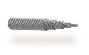 AAAC — Aluminum Alloy Conductor
AAAC conductor, AAAC conductor manufacturer, all aluminum alloy conductor, AAAC cable, ASTM B399 AAAC, aluminum alloy overhead conductor, overhead transmission conductor, overhead distribution conductor, AAAC 6201, bare overhead conductor
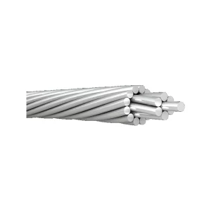 AAC — All Aluminum Conductor
AAC conductor, AAC conductor manufacturer, all aluminium conductor, all aluminum conductor, AAC cable, aluminum stranded conductor, aluminium stranded conductor, Aluminum 1350-H19 conductor, ASTM B230, ASTM B231, AS/NZS 1531, DIN 48201 Part 5, GOST 839-80, BS 215-1, BS EN 50182, IEC 61089, bare overhead conductor, overhead distribution conductor.
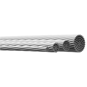 High Conductivity Aluminium Alloy Conductor (AAAC) – AL5, AL6, AL7, AL57, AL59 & Alloy 1120
high conductivity aluminium alloy conductor, AAAC conductor, AAAC manufacturer, AL5 conductor, AL6 conductor, AL7 conductor, AL57 conductor, AL59 conductor, Alloy 1120 conductor, high conductivity AAAC, aluminium alloy overhead conductor, overhead transmission conductor, BS EN 50182
AAAC AL7 Conductor – All Aluminium Alloy Conductor
AAAC conductor, AAAC AL7, AL7 conductor, AL7 aluminium alloy conductor, all aluminium alloy conductor, aluminium alloy overhead conductor, AAAC conductor manufacturer, EN 50182 conductor, overhead transmission conductor, overhead distribution conductor
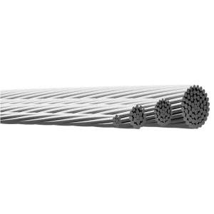 AAAC (AL59) Conductor – High-Strength Aluminium Alloy Conductor
AAAC conductor, AAAC AL59, AL59 conductor, aluminum alloy conductor, all aluminium alloy conductor, AAAC conductor manufacturer, SS 424 08 14, SS EN 50182, overhead alloy conductor, stranded aluminum alloy conductor, grease filled AAAC conductor
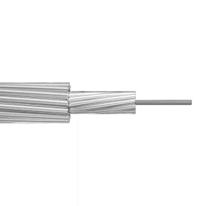 ACSR — Aluminum Conductor Steel Reinforced
ACSR conductor, ACSR conductor manufacturer, ACSR cable, ACSR/AW conductor, ACSR/TW conductor, aluminum conductor steel reinforced, aluminum clad steel reinforced conductor, trapezoidal wire ACSR, overhead transmission conductor, bare overhead conductor, ASTM B232, ASTM B549, ASTM B779, IEC 61089.
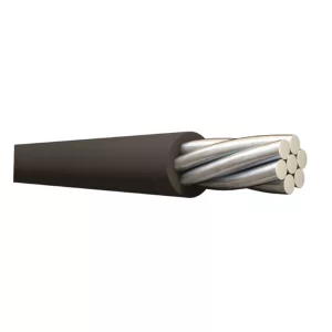 PVC-Covered Aluminium Conductors – AAC & ACSR
PVC covered aluminium conductor, PVC covered conductor, PVC covered overhead wire, PVC covered AAC conductor, PVC covered ACSR conductor, PVC insulated aluminium conductor, stranded aluminium overhead conductor, PVC covered power line conductor, BS 6485 conductor, BS 215 conductor
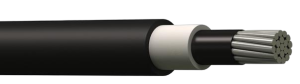 Covered Aerial Medium Voltage Cable – Spacer Cable & Tree Wire
Tree Wire Cable, Spacer Cable, Medium Voltage Overhead Cable, Messenger Supported Spacer Cable, Covered Overhead Conductor, Track Resistant XLPE Cable, XLPE Covered Conductor, ICEA S-121-733, AAC Tree Wire, AAAC Spacer Cable, ACSR Tree Wire
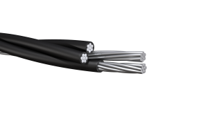 ANSI — Service Drop Cable
This duplexed cable is suited for supply 120 volts aerial service for temporary service at construction sites, outdoor or street lighting. For service at 600 volts or lower at conductor temperatures not to exceed 75°C for polyethylene insulated conductors or 90°C for crosslinked polyethylene (XLP)…
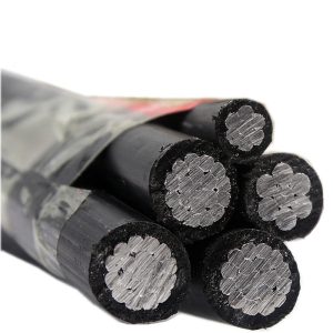 0.61k V LV ABC Cable Aerial Bundle Conductor
The aerial bundled cables designed for overhead distribution lines have all conductors made of aluminium 1350 and insulated with XLPE. Can be used for fixed installation as overhead power lines up to 1000 V incl.
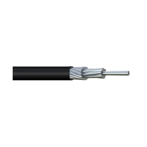 600V Covered Overhead Line Wire – AAC, AAAC & ACSR
600V covered conductor, covered overhead line wire, covered line wire manufacturer, AAC covered conductor, AAAC covered conductor, ACSR covered conductor, aluminium covered conductor, LDPE covered conductor, HDPE covered conductor, XLPE covered conductor, overhead secondary distribution wire
Related solutions
Power Generation Cable Solutions
QZ Cable supplies power generation cable solutions for thermal, hydro, solar and wind power projects, including LV/MV power cables, control cables, instrumentation cables and overhead conductors.
Power Transmission Cable Solutions
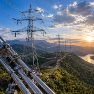
QZ Cable supplies power transmission solutions, including AAC, AAAC, ACSR, ACSS, TACSR, TAAAC, OPGW and ADSS for utility, grid expansion and EPC projects worldwide.
Power Distribution Cable Solutions
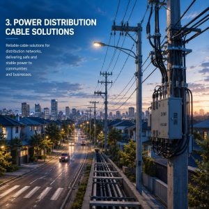
Qingzhou Cable provides low- and medium-voltage cable solutions for electrical distribution networks, supporting power delivery from substations to commercial, industrial and residential users.
Power Substation Cable Solutions
Solar & Renewable Energy Cable Solutions