
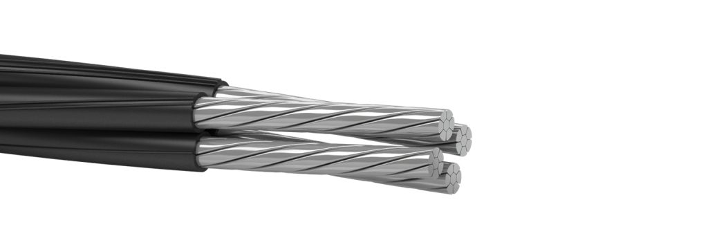
Self-supporting Insulated (SIP) Cables SIP-1, SIPn-1, SIP-2, SIPn-2, SIP-4, SIPn-4, SIP-5, SIP-5ng
Self-supporting Insulated (SIP) Cables SIP-1, SIPn-1, SIP-2, SIPn-2, SIP-4, SIPn-4, SIP-5, SIP-5ng
- Standards: GOST R 52373-2005 · GOST 15150-69
Product Description
Self-supporting Insulated (SIP) Cables SIP-1, SIPn-1, SIP-2, SIPn-2, SIP-4, SIPn-4, SIP-5, SIP-5ng
Self supporting insulated wires (Aerial Bundled Conductor) SIP per GOST R 52373-2005 and TU 16-705.500-2006
(TU 16-705.500-2006 used instead of TU 16.К71-268-98 and TU 16.К71- 272-98)
Self-supporting Wire Description
SIP is a self-supporting insulated wire which is intended to transfer electrical energy in overhead power lines and branch off from trunk lines to enter into residential buildings and utility buildings. The laying is carried out on supports, as well as on the walls and structural elements of industrial and residential buildings.
AsXS is a self-supporting wire for overhead power lines with aluminum conductors, insulated with XLPE, resistant to ultraviolet.
AsXSn is a self-supporting wire with aluminum conductors, insulated with XLPE, resistant to ultraviolet, flame retardant.
The wires are designed for the transmission and distribution of electrical energy in power and lighting networks for an alternating voltage 0.6/1 kV.
The insulated wires with a neutral self-supporting conductor (SIP-1 and SIP-2) are intended for installation and reconstruction of overhead power transmission lines and linear branches from overhead lines, as well as descents to power electrical equipment.
The insulated wires without a neutral self-supporting conductor (SIP-4, SIP-5 and AsXS, AsXSn) are intended for the branches from overhead power lines to the enter, and for the laying along the walls of buildings and structures.
INTERPRETATION OF WIRES SIP-1, SIPN-1, SIP-2, SIPN-2, SIP-4, SIPN-4, SIP-5, SIP-5NG, ASXS, ASXSN
S – self-supporting;
I – insulated;
P – wire;
n, ng – does not support combustion.
A – aluminum conductor;
s – self-supporting wire;
XS – insulation made of cross-linked polyethylene;
n – does not support combustion.
Self-supporting Insulated (SIP) Cables Application
SIP-1 – for overhead transmission lines (TL) and linear TL deviations in atmosphere types I and II as per GOST 15150-69
SIP-2 – for overhead transmission lines (TL) and linear TL deviations in atmosphere types I and II as per GOST 15150-69 , including sea coasts, salt lakes shores, in industrial areas and halopsammophilous areas
SIP-3 – for TL with nominal voltage 10-35 kV in atmosphere types II and III as per GOST 15150-69 , including sea coasts, salt lakes shores, in industrial areas and halopsammophilous areas
SIP-4 – for TL deviations to entry and for laying in walls of buildings and engineering structures in
atmosphere types II and III as per GOST 15150-69
Self-supporting Insulated (SIP) Cables Construction
The number in the wire marking indicates the type of construction.
SIP-1 – with a non-insulated neutral self-supporting conductor;
SIP-2 – with an insulated neutral self-supporting conductor;
SIP-4 – without neutral self-supporting conductor with light-stabilized polyethylene insulation;
SIP-5 – without neutral self-supporting conductor, insulated with silanol-crosslinked light-stabilized polyethylene.
1. CONDUCTING CORE – Al, round core, for all cross-section the core is compacted multiwire, the quantity of wire in phase core. Outer diameter of conducting core and its electrical resistance shown in bellow table:
| Nominal cross-section of phase core, mm2 | Number of wires in the core, units. | Outer diameter of conducting core, mm | Electrical resistance of 1 km of phase core to DC, ohm not more | |
|---|---|---|---|---|
| Min. | Max. | |||
| 16 | 7 | 4,6 | 5,1 | 1,910 |
| 25 | 7 | 5,7 | 6,1 | 1200 |
| 35 | 7 | 6,7 | 7,1 | 0,868 |
| 50 | 7 | 7,85 | 8,35 | 0,641 |
| 70 | 7 | 9,45 | 9,95 | 0,443 |
| 95 | 7 | 11,1 | 11,7 | 0,320 |
| 120 | 19 | 11,1 | 13,1 | 0,253 |
| 150 | 19 | 14,0 | 14,5 | 0,206 |
| 185 | 19 | 15,45 | 16,15 | 0,164 |
| 240 | 19 | 17,75 | 18,45 | 0,125 |
2. NEUTRAL MESSENGING CORE – form Al alloy, round core, stranded from round wires, compacted. Nominal cross-sections, number of wires in the core, outer diameter of core, its burst capacity and electrical resistance are specified in the bellow table:
| Nominal cross-section of phase core, mm2 | Number of wires in the core, units. | Outer diameter of conducting core, mm | Electrical resistance of 1 km of phase core to DC, ohm not more | |
|---|---|---|---|---|
| Min. | Max. | |||
| 25 | 7 | 5,7 | 6,1 | 1,380 |
| 35 | 7 | 6,7 | 7,1 | 0,986 |
| 50 | 7 | 7,85 | 8,35 | 0,720 |
| 54,6 | 7 | 9,2 | 9,6 | 0,630 |
| 70 | 7 | 9,45 | 9,95 | 0,493 |
| 95 | 7 | 11,1 | 11,7 | 0,363 |
| 120 | 19 | 12,2 | 12,9 | 0,288 |
| 150 | 19 | 13,9 | 14,5 | 0,236 |
| 185 | 19 | 15,75 | 16,15 | 0,188 |
| 240 | 19 | 17,75 | 18,45 | 0,145 |
3. INSULATION – in SIP-1 the neutral core is not insulated. In other conductors the insulation made from light-stabilized cross-linked PE. Insulated phase cores have the distinctive coloring. Insulation thickness is shown in the following table:
| Types of wire |
Nominal isulation thickness, mm | ||||||||||
| 16 | 25 | 35 | 50 | 54,6 | 70 | 95 | 120 | 150 | 185 | 240 | |
| SIP-1 | 1,3 | 1,3 | 1,3 | 1,5 | 1,5 | 1,7 | 1,7 | 1,7 | 1,7 | 1,9 | 1,9 |
| SIP-2 | |||||||||||
| SIP-3 20 kV | 2,3 | ||||||||||
| SIP-3 35 kV | 3,5 | ||||||||||
| SIP-4 | 1,3 | 1,3 | |||||||||
4. STRANDING – insulated phase cores are stranded round a bearing neutral core. Stranding direction is right-hand. On the customer’s request it is permissible to manufacture SIP-1 and SIP-2 with auxiliary insulated lead with cross-section 16 and 25 mm2 for lighting circuit connection.
TECHNICAL SPECIFICATION
Type of climatization is UHL, allocation category are 1, 2 and 3 as per GOST 15150-69.
Conductors are resistant to solar radiation characterized by warmth fluence 1120 W/m2±10%, including density of ultraviolet part of spectrum 68 W/m2±25%.
Conductors are resistant to bending at the temperature………………………………………………………………..-40°C
Cabling and installation should be carried out at ambient temperature not less than ………………………………………….-20°C
Permissible forces in a neutral supporting conductor at tension and while exploiting are not greater than…………………………..45 N/mm2
Insulated cores of wires should withstand the test by AC voltage 3.5 kV and frequency 50 Hz in passing
After standing in the water at the temperature 20°C not less 10 min the conductors should withstand
AC voltage test 50 Hz during 5 minutes with the following values:
For SIP-1, SIP-2 and SIP-4 conductors………………………………………………4 kV
For SIP-3 conductors for 20 kV………………………………………………………6 kV
For SIP-3 conductors for 35 kV………………………………………………………10 kV
Conductors withstand the test by AC voltage 4 kV frequency 50 Hz during 1 hour.
Permissible conducting cores heating temperature is not more than +90°С in normal conditions and 250°C at short-circuit.
Allowable conductor current load estimated at the ambient temperature +25°C, wind speed 0.6 m/s and solar radiation intensity 1000 W/m2.
Permissible one-second short-circuit currents:
| Nominal cross-section of main cores, mm | Permissible current load, A, not more | Permissible one-second short-circuit current, kA, not more | |||
|---|---|---|---|---|---|
| of self supporting insulated wire | of protected wire | of self supporting insulated wire | of protected wire | ||
| 25kV | 35kV | ||||
| 16 | 100 | – | – | 1,5 | – |
| 25 | 130 | – | – | 2,3 | – |
| 35 | 160 | 200 | 220 | 3,2 | 3,0 |
| 50 | 195 | 245 | 270 | 4,6 | 4,3 |
| 70 | 240 | 310 | 340 | 6,5 | 6,0 |
| 95 | 300 | 370 | 400 | 8,8 | 8,2 |
| 120 | 340 | 430 | 460 | 10,9 | 10,3 |
| 150 | 380 | 485 | 520 | 13,2 | 12,9 |
| 185 | 436 | 560 | 600 | 16,5 | 15,9 |
| 240 | 515 | 600 | 670 | 22,0 | 20,6 |
SIP-1 SIP-2 SIP-3 SIP-4 Aluminum Cable Specifications
| Mark and rated voltage wire | Number and nominal cross-phase and zero bearing veins sht.h mm2 | Estimate the outer diameter of wire, mm | Estimated weight of 1 km of wire, kg |
|---|---|---|---|
| SIP-1 0,6 / 1 kV | 1х16+1х25 | 15 | 135 |
| 3х16+1х25 | 22 | 270 | |
| 3х25+1х35 | 26 | 390 | |
| 3х35+1х50 | 30 | 530 | |
| 3х50+1х50 | 32 | 685 | |
| 3х50+1х70 | 35 | 740 | |
| 3х70+1х70 | 37 | 930 | |
| 3х70+1х95 | 41 | 990 | |
| 3х95+1х70 | 41 | 1190 | |
| 3х95+1х95 | 43 | 1255 | |
| 3х120+1х95 | 46 | 1480 | |
| 3х150+1х95 | 48 | 1715 | |
| 3х185+1х95 | 52 | 2330 | |
| 3х240+1х95 | 56 | 2895 | |
| SIP-2 0,6 / 1 kV | 3х16+1х25 | 24 | 308 |
| 3х16+1х54,6* | 28 | 427 | |
| 3х25+1х35 | 27 | 424 | |
| 3х25+1х54,6* | 30 | 512 | |
| 3х35+1х50 | 31 | 571 | |
| 3х35+1х54,6* | 32 | 606 | |
| 3х50+1х50 | 34 | 727 | |
| 3х50+1х54,5* | 35 | 762 | |
| 3х50+1х70 | 36 | 798 | |
| 3х70+1х54,6* | 39 | 973 | |
| 3х70+1х70 | 40 | 1010 | |
| 3х70+1х95 | 41 | 1087 | |
| 3х95+1х70 | 43 | 1240 | |
| 3х95+1х95 | 45 | 1319 | |
| 3х120+1х95 | 48 | 1553 | |
| 3х150х1х95 | 50 | 1787 | |
| 3х185+1х95 | 55 | 2403 | |
| 3х240+1х95 | 60 | 2968 | |
| SIP-3 20 kV | 1х35 | 12 | 165 |
| 1х50 | 13 | 215 | |
| 1х70 | 15 | 282 | |
| 1х95 | 16 | 364 | |
| 1х120 | 18 | 445 | |
| 1х150 | 19 | 540 | |
| 1х185 | 24 | 722 | |
| 1х240 | 24 | 950 | |
| SIP-3 20 kV | 1х35 | 14 | 209 |
| 1х50 | 16 | 263 | |
| 1х70 | 17 | 334 | |
| 1х95 | 19 | 421 | |
| 1х120 | 20 | 518 | |
| 1х150 | 22 | 618 | |
| 1х185 | 24 | 808 | |
| 1х240 | 26 | 1045 | |
| SIP-4 0,6/1 kV | 2х16 | 15 | 139 |
| 4х16 | 18 | 278 | |
| 2х25 | 17 | 196 | |
| 4х25 | 21 | 392 |
SIP-1, SIPn-1 Parameter
| Number of conductors and nominal cross-section, mm2 | Nominal outer diameter, mm | Weight of 1 km of wire, kg |
|---|---|---|
| 1 x 16 + 1 x 25 | 13,4 | 136 |
| 3 x 16 + 1 x 25 | 17,8 | 274 |
| 3 x 25 + 1 x 35 | 20,8 | 392 |
| 3 x 35 + 1 x 50 | 23,4 | 517 |
| 3 x 50 + 1 x 50 | 26,0 | 654 |
| 3 x 50 + 1 x 70 | 27,1 | 710 |
| 3 x 70 + 1 x 70 | 30,8 | 931 |
| 3 x 70 + 1 x 95 | 32,1 | 1002 |
| 3 x 95 + 1 x 70 | 33,7 | 1174 |
| 3 x 95 + 1 x 95 | 34,9 | 1246 |
| 3 x 120 + 1 x 95 | 38,2 | 1470 |
| 3 x 150 + 1 x 95 | 40,5 | 1697 |
| 3 x 185 + 1 x 95 | 45,0 | 2065 |
| 3 x 240 + 1 x 95 | 50,1 | 2521 |
SIP-2, SIPn-2 Parameter
| Number of conductors and nominal cross-section, mm2 | Nominal outer diameter, mm | Weight of 1 km of wire, kg |
|---|---|---|
| 3 x 16 + 1 x 25 | 20,6 | 306 |
| 3 x 25 + 1 x 35 | 21,8 | 428 |
| 3 x 25 + 1 x 54,6 | 23,2 | 489 |
| 3 x 35 + 1 x 50 | 24,6 | 566 |
| 3 x 35 + 1 x 54,6 | 25,0 | 581 |
| 3 x 50 + 1 x 50 | 27,1 | 703 |
| 3 x 50 + 1 x 54,6 | 27,7 | 718 |
| 3 x 50 + 1 x 70 | 28,6 | 777 |
| 3 x 70 + 1 x 54,6 | 32,1 | 939 |
| 3 x 70 + 1 x 70 | 32,1 | 997 |
| 3 x 70 + 1 x 95 | 33,5 | 1078 |
| 3 x 95 + 1 x 70 | 36,4 | 1241 |
| 3 x 95 + 1 x 95 | 36,4 | 1322 |
| 3 x 120 + 1 x 95 | 39,8 | 1546 |
| 3 x 150 + 1 x 95 | 43,8 | 1773 |
| 3 x 185 + 1 x 95 | 46,7 | 2141 |
| 3 x 240 + 1 x 95 | 50,1 | 2598 |
SIP-4, SIPn-4, SIP-5, SIP-5ng, AsXS, AsXSn Parameter
| Number of conductors and nominal cross-section, mm2 | Nominal outer diameter, mm | Weight of 1 km of wire, kg |
|---|---|---|
| 1 x 10 | 6,2 | 47 |
| 1 x 16 | 7,4 | 68 |
| 1 x 25 | 8,6 | 98 |
| 1 x 35 | 9,7 | 129 |
| 1 x 50 | 11,3 | 174 |
| 1 x 70 | 13,3 | 246 |
| 1 x 95 | 15,1 | 327 |
| 1 x 120 | 16,5 | 401 |
| 1 x 150 | 18,2 | 475 |
| 1 x 185 | 20,2 | 596 |
| 1 x 240 | 22,5 | 747 |
| 2 x 10 | 12,4 | 94 |
| 2 x 16 | 14,8 | 138 |
| 2 x 25 | 17,2 | 199 |
| 2 x 35 | 19,4 | 260 |
| 2 x 50 | 22,5 | 351 |
| 2 x 70 | 26,6 | 499 |
| 2 x 95 | 30,2 | 661 |
| 2 x 120 | 33,1 | 811 |
| 2 x 150 | 36,3 | 962 |
| 2 x 185 | 40,4 | 1207 |
| 2 x 240 | 44,9 | 1512 |
| 3 x 10 | 13,4 | 142 |
| 3 x 16 | 15,9 | 207 |
| 3 x 25 | 18,5 | 298 |
| 3 x 35 | 20,8 | 391 |
| 3 x 50 | 24,2 | 527 |
| 3 x 70 | 28,6 | 748 |
| 3 x 95 | 32,4 | 991 |
| 3 x 120 | 35,5 | 1216 |
| 3 x 150 | 39,0 | 1443 |
| 3 x 185 | 43,4 | 1811 |
| 3 x 240 | 48,3 | 2267 |
| 4 x 10 | 15,0 | 189 |
| 4 x 16 | 17,8 | 276 |
| 4 x 25 | 20,8 | 397 |
| 4 x 35 | 23,4 | 521 |
| 4 x 50 | 27,1 | 703 |
| 4 x 70 | 32,1 | 997 |
| 4 x 95 | 36,4 | 1322 |
| 4 x 120 | 39,8 | 1621 |
| 4 x 150 | 43,8 | 1924 |
| 4 x 185 | 48,7 | 2415 |
| 4 x 240 | 54,2 | 3023 |
Applicable Standards
Certificate Display
Type and routine tests are issued from our own testing centre under the ISO 9001 quality system — test reports and certificates accompany every shipment.
Factory Tour
Why Choose Us
Packing & Shipping
- Wooden, steel or steel-wood drums; drum length to customer requirement
- Drum marking per customer / utility specification
- Both drum ends sealed and protected for sea freight
Ready for Your Next Cable Project?
Send us your specifications, cable schedule or RFQ — our engineering team replies with a technical proposal and price within one working day.
- Emailinfo@qzcablegroup.com
- WhatsApp / WeChat+86 173 3570 4553
- Contact personChloe · Export Department
- Factory addressWest Industrial Park, Zhulin Town, Gongyi City, Henan Province, China
Related products
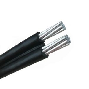 16mm2 Twin Conductor Wire AAC PVC Parallel Aluminum Cable
16mm2 Twin Conductor Wire AAC PVC Parallel Aluminum Cable
16mm2 Twin Conductor Wire AAC PVC Parallel Aluminum Cable
 POLY AL. POLY AAC POLY ACSR
POLY AL. POLY AAC POLY ACSR
POLY AL. POLY AAC POLY ACSR
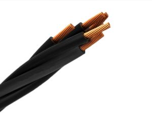 XS — Copper Aluminium Overhead Aerial Bundle Cable
DMA C33-209 XS/LXS Copper/Aluminium Overhead Aerial Bundle Cable
XS — Copper Aluminium Overhead Aerial Bundle Cable
DMA C33-209 XS/LXS Copper/Aluminium Overhead Aerial Bundle Cable
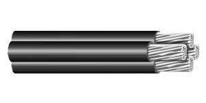 E-A2Y — Insulated Self-supporting Aerials Cables
OVE E 8200-626 E-A2Y - PE Insulated Self-supporting Aerials Cables
E-A2Y — Insulated Self-supporting Aerials Cables
OVE E 8200-626 E-A2Y - PE Insulated Self-supporting Aerials Cables
Related solutions
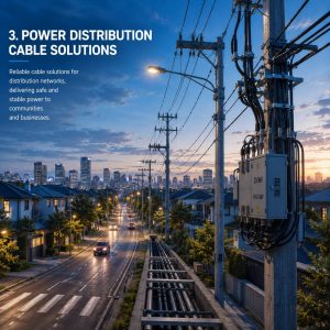
Power Distribution Cable Solutions
Qingzhou Cable provides low- and medium-voltage cable solutions for electrical distribution networks, supporting power delivery from substations to commercial, industrial and residential users.
Power Substation Cable Solutions
Solar & Renewable Energy Cable Solutions
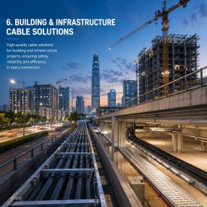
Building & Infrastructure Cable Solutions

Mining Cable Solutions