ANTI-FRAUD COPPER ALUMINUM- SEU SER
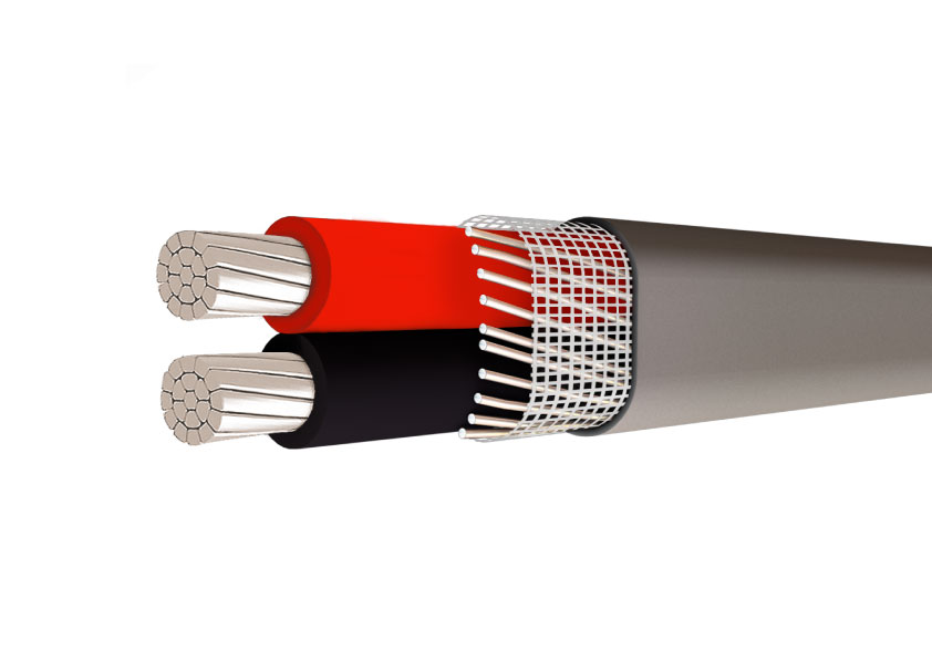
Type SE, service entrance cable is primarily used to convey power from the service drop to the meter base and from the meter base to the distribution panel board
- Constructed with sunlight resistant Type XHHW-2 conductors or Type THHN/THWN conductors.
- • ASTM- All applicable standards
Product Description
ANTI-FRAUD COPPER ALUMINUM- SEU SER
Type SE, service entrance cable is primarily used to convey power from the service drop to the meter base and from the meter base to the distribution panel board
COPPER SERVICE ENTRANCE CONCENTRIC CABLE American Standard-SE SER SEU TYPE
Application
Type SE, service entrance cable is primarily used to convey power from the service drop to the meter base and from the meter base to the distribution panel board; however, the cable may be used in all applications where Type SE cable is permitted. SER may be used in wet or dry locations at temperatures not to exceed 90°C. Voltage rating is 600 volts.
Standard
- ASTM- All applicable standards
- UL Standard 44 for XHHW-2 conductors
- UL Standard 83 for THHN/THWN conductors
- UL Standard 854
- Federal Specification A-A-59544
- National Electrical Code, NFPA 70. 2011 Edition
Construction
Constructed with sunlight resistant Type XHHW-2 conductors or Type THHN/THWN conductors.
Copper conductors are annealed (soft) copper. Cable assembly plus reinforcement tape are jacketed with sunlight resistant
gray polyvinyl chloride (PVC). Available as 1 conductor with a concentric ground, 2 conductor with a round or concentric
ground, or 3 conductor with a bare ground. SE cable is jacketed with gray sunlight resistant polyvinyl chloride (PVC).
PARAMETER
SER Copper Conductor
|
Size/ Construction (AWG) |
Stranding |
Nominal O.D. (mils) |
Approximate Weight per 1000′ (lbs) |
Allowable Ampacities+ |
Standard Package |
||||
|
Phase & Neutral Conductors |
Equipment Ground Conductor |
60° C |
75° C |
90° C |
Dwelling |
||||
|
SER Copper TWO CONDUCTOR WITH BARE GROUND (FORMERLY REFERRED TO AS “THREE CONDUCTOR”) |
|||||||||
|
8-8-8 |
7 |
– – |
586 |
231 |
40 |
50 |
55 |
– – |
B |
|
6-6-6 |
7 |
– – |
669 |
338 |
55 |
65 |
75 |
– – |
B |
|
4-4-4 |
7 |
– – |
764 |
498 |
70 |
85 |
95 |
100 |
B |
|
3-3-3 |
7 |
– – |
829 |
611 |
85 |
100 |
110 |
110 |
B |
|
2-2-2 |
7 |
– – |
896 |
752 |
95 |
115 |
130 |
125 |
B |
|
1-1-1 |
19 |
– – |
1021 |
948 |
110 |
130 |
150 |
150 |
C |
|
1/0-1/0-1/0 |
19 |
– – |
1114 |
1169 |
125 |
150 |
170 |
175 |
C |
|
2/0-2/0-2/0 |
19 |
– – |
1209 |
1444 |
145 |
175 |
195 |
200 |
C |
|
3/0-3/0-3/0 |
19 |
– – |
1317 |
1792 |
165 |
200 |
225 |
225 |
C |
|
4/0-4/0-4/0 |
19 |
– – |
1438 |
2226 |
195 |
230 |
260 |
250 |
C |
|
SER Copper THREE CONDUCTOR WITH BARE GROUND (FORMERLY REFERRED TO AS “FOUR CONDUCTOR”) |
|||||||||
|
8-8-8-8 |
7 |
7 |
645 |
286 |
40 |
50 |
55 |
– – |
B |
|
6-6-6-6 |
7 |
7 |
738 |
424 |
55 |
65 |
75 |
– – |
B |
|
4-4-4-6 |
7 |
7 |
844 |
585 |
70 |
85 |
95 |
100 |
B |
|
3-3-3-5 |
7 |
7 |
910 |
719 |
85 |
100 |
110 |
110 |
B |
|
2-2-2-4 |
7 |
7 |
984 |
887 |
95 |
115 |
130 |
125 |
B |
|
1-1-1-3 |
19 |
7 |
1132 |
1117 |
110 |
130 |
150 |
150 |
C |
|
1/0-1/0-1/0-2 |
19 |
19 |
1235 |
1382 |
125 |
150 |
170 |
175 |
C |
|
2/0-2/0-2/0-1 |
19 |
19 |
1342 |
1713 |
145 |
175 |
195 |
200 |
C |
|
3/0-3/0-3/0-1/0 |
19 |
19 |
1462 |
2129 |
165 |
200 |
225 |
225 |
C |
|
4/0-4/0-4/0-2/0 |
19 |
19 |
1598 |
2650 |
195 |
230 |
260 |
250 |
C |
|
Table values reflect XHHW-2 conductors Allowable ampacities shown are for general use as specified by the National Electrical Code, 2011 Edition, section 310.15 and 240.4(D). Unless the is marked for use at higher temperaturesthe conductor ampacities shall be limited to the following per NEC 110.14(C) 60 ° C When terminated to equipment for circuits rated 100 amperes or less or marked for 14 – 1 AWG conductors. 75 ° C When terminated to equipment for circuits rated over 100 amperes or marked for conductors larger than 1 AWG . 90 ° C XHHW wet or Dry locations for ampacity adjustment purposes using NEC section 310.15 For dwelling ampacity use section 310.15(B)(7) |
Package Code B- 1000′ Reel C- 500′ Reel |
||||||||
SEU Copper Conductor
|
Conductor |
Stranding |
Nominal O.D. (mils) |
Approximate Weight per 1000′ (lbs) |
Allowable Ampacities+ |
Standard Package |
||||
|---|---|---|---|---|---|---|---|---|---|
|
Size (AWG) |
Phase Conductors |
Bare Ground |
60° C |
75° C |
90° C |
Dwelling |
|||
|
SEU Copper ONE CONDUCTOR WITH A BARE CONCENTRIC GROUND (FORMALLY REFERRED TO AS “TWO CONDUCTOR”) |
|||||||||
|
8-8 |
7 |
8 |
400 |
144 |
40 |
50 |
55 |
– – |
ABC |
|
6-6 |
7 |
12 |
435 |
208 |
55 |
65 |
75 |
– – |
|
|
4-4 |
7 |
12 |
506 |
315 |
70 |
85 |
95 |
– – |
C |
|
2-2 |
7 |
15 |
580 |
485 |
95 |
115 |
130 |
– – |
|
|
SEU Copper TWO CONDUCTOR WITH A BARE CONCENTRIC GROUND (FORMALLY REFERRED TO AS “THREE CONDUCTOR”) |
|||||||||
|
10-10-10 |
1 |
12 |
428 X 283 |
127 |
30 |
30 |
30 |
– – |
ABC |
|
8-8-8 |
7 |
8 |
587 X 380 |
211 |
40 |
50 |
60 |
– – |
ABC |
|
6-6-6 |
7 |
12 |
659 X 416 |
308 |
55 |
65 |
75 |
– – |
BCE |
|
4-4-4 |
7 |
12 |
815 X 506 |
471 |
70 |
85 |
95 |
100 |
BCE |
|
3-3-3 |
7 |
12 |
883 X 548 |
583 |
85 |
100 |
110 |
110 |
B |
|
2-2-2 |
7 |
15 |
994 X 578 |
718 |
95 |
115 |
130 |
125 |
BD |
|
1-1-1 |
19 |
14 |
1093 X 664 |
904 |
110 |
130 |
150 |
150 |
B |
|
1/0-1/0-1/0 |
19 |
18 |
1179 X 707 |
1123 |
125 |
150 |
170 |
175 |
BC |
|
2/0-2/0-2/0 |
19 |
18 |
1283 X 767 |
1379 |
145 |
175 |
195 |
200 |
BC |
|
3/0-3/0-3/0 |
19 |
14 |
1429 X 862 |
1712 |
165 |
200 |
225 |
225 |
BD |
|
4/0-4/0-4/0 |
19 |
18 |
1541 X 918 |
2146 |
195 |
230 |
260 |
250 |
BC |
|
SEU Copper TWO CONDUCTOR WITH A BARE CONCENTRIC GROUND (FORMALLY REFERRED TO AS “THREE CONDUCTOR”) (REDUCED NEUTRAL) |
|||||||||
|
6-6-8 |
7 |
8 |
659 X 416 |
281 |
55 |
65 |
75 |
– – |
BC |
|
4-4-6 |
7 |
12 |
790 X 481 |
420 |
70 |
85 |
95 |
100 |
BC |
|
3-3-5 |
7 |
15 |
843 X 508 |
515 |
85 |
100 |
110 |
110 |
BC |
|
2-2-4 |
7 |
12 |
929 X 563 |
639 |
95 |
115 |
130 |
125 |
BC |
|
Table values reflect XHHW-2 conductors Allowable ampacities shown are for general use as specified by the National Electrical Code, 2011 Edition, section 310.15 and 240.4(D). Unless the is marked for use at higher temperaturesthe conductor ampacities shall be limited to the following per NEC 110.14(C) 60 ° C When terminated to equipment for circuits rated 100 amperes or less or marked for 14 – 1 AWG conductors. 75 ° C When terminated to equipment for circuits rated over 100 amperes or marked for conductors larger than 1 AWG . 90 ° C XHHW wet or Dry locations for ampacity adjustment purposes using NEC section 310.15 For dwelling ampacity use section 310.15(B)(7) |
Package Code: A- 250′ Coil B- 500′ Reel C- 1000′ Reel D- 100′ Reel E- 150′ Coil |
||||||||
ALUMINUM SERVICE ENTRANCE CONCENTRIC CABLE American Standard-SE SER SEU TYPE
Application
Type SE, service entrance cable is primarily used to convey power from the service drop to the meter base and from the meter base to the distribution panel board; however, the cable may be used in all applications where Type SE cable is permitted. SER may be used in wet or dry locations at temperatures not to exceed 90°C. Voltage rating is 600 volts.
Standard
- ASTM- B-800 and B-801
- UL Standard 83 for THHN/THWN-2
- UL Standard 44 for XHHW-2
- Federal Specification A-A-59544
- National Electrical Code/NFPA 70, 2011 Edition
- RoHS
Construction
Type SE cable is constructed with AA-8000 series aluminum alloy, compact stranded conductors. The conductors are covered with a sunlight resistant Type XHHW-2 or Type THHN/THWN-2 insulation. A reinforcement tape is wrapped around the conductors for added strength and conformity. A gray sunlight resistant polyvinyl chloride (PVC) outer jacket covers the entire assembly. Style SEU cable has two phase conductors surrounded by a concentric neutral while the SER style has two, three or four phase conductors and a bare neutral.
Style SER Cable’s phase conductors are identified by a colored stripe on the insulation.
3 conductor- Black and Black with Red Stripe
4 conductor- Black, Black with White Stripe, and Black with Red Stripe
5 conductor- Black, Black with White Stripe, Black with Red Stripe and Black with Blue Stripe
PARAMETER
SER SEU Aluminum Conductor
| Conductor | Stranding* | Nominal O.D. (mils) | Allowable Ampacities+ | Approx. Net Weight per 1000′ (lbs) | Standard Package | ||||
|---|---|---|---|---|---|---|---|---|---|
| Size/Const. AWG or kcmil | Phase Conductor & Neutral | Equipment Ground Conductor | 60° C | 75° C | 90° C | Dwelling | |||
| SER Aluminum Two Conductor With Bare Ground (Formerly referred to as “EZ-SE”) | |||||||||
| 6-6-6 | 7 | – | 650 | 40 | 50 | 60 | – | 150 | B |
| 4-4-4 | 7 | – | 745 | 55 | 65 | 75 | – | 203 | B |
| 4-4-6 | 7 | – | 745 | 55 | 65 | 75 | – | 203 | B |
| 2-2-2 | 7 | – | 864 | 75 | 90 | 100 | 100 | 290 | B |
| 2-2-4 | 7 | – | 864 | 75 | 90 | 100 | 100 | 290 | B |
| 2/0-2/0-1 | 12 | – | 1140 | 115 | 135 | 150 | 150 | 527 | B |
| 2/0-2/0-2/0 | 12 | – | 1140 | 115 | 135 | 150 | 150 | 527 | B |
| 4/0-4/0-2/0 | 19 | – | 1354 | 150 | 180 | 205 | 200 | 784 | C |
| 4/0-4/0-4/0 | 19 | – | 1354 | 150 | 180 | 205 | 200 | 784 | C |
| SER Aluminum Three Conductor With Bare Ground (Formerly referred to as “Four Conductor”) | |||||||||
| 8-8-8-8 | 1 | 1 | 612 | 30 | 40 | 45 | – | 136 | B |
| 6-6-6-6 | 7 | 7 | 717 | 40 | 50 | 60 | – | 196 | B |
| 4-4-4-6 | 7 | 7 | 823 | 55 | 65 | 75 | – | 252 | B |
| 2-2-2-4 | 7 | 7 | 956 | 75 | 90 | 100 | 100 | 359 | B |
| 1-1-1-3 | 8 | 7 | 1079 | 85 | 100 | 115 | 110 | 449 | C |
| 1/0-1/0-1/0-2 | 10 | 1 | 1168 | 100 | 120 | 135 | 125 | 540 | C |
| 2/0-2/0-2/0-1 | 12 | 1 | 1264 | 115 | 135 | 150 | 150 | 652 | C |
| 3/0-3/0-3/0-1/0 | 16 | 1 | 1371 | 130 | 155 | 175 | 175 | 786 | C |
| 4/0-4/0-4/0-2/0 | 19 | 1 | 1496 | 150 | 180 | 205 | 200 | 960 | C |
| 250-250-250-3/0 | 22 | 1 | 1839 | 170 | 205 | 230 | 225 | 1458 | C |
| SER Aluminum Four Conductor With Bare Ground (Formerly referred to as “Five Conductor”) | |||||||||
| 2-2-2-2-4 | 6 | 7 | 1059 | 75 | 90 | 100 | 100 | 452 | B 5 |
| 2/0-2/0-2/0-2/0-1 | 12 | 1 | 1404 | 115 | 135 | 150 | 150 | 827 | C |
| 4/0-4/0-4/0-4/0-2/0 | 19 | 1 | 1672 | 150 | 180 | 205 | 200 | 1228 | C |
| 50-250-250-250-3/0 | 22 | 1 | 1847 | 170 | 205 | 230 | 225 | C | |
| SEU Aluminum Two Conductor With Bare Concentric Ground (Formerly referred to as “Three Conductor”) | |||||||||
| 6-6-6 | 7 | 8 | 430 X 687 | 40 | 50 | 60 | – | 145 | H |
| 4-4-4 | 7 | 12 | 499 X 800 | 55 | 65 | 75 | – | 198 | I |
| 4-4-6 | 7 | 15 | 474 X 775 | 55 | 65 | 75 | – | 181 | I |
| 2-2-2 | 7 | 14 | 569 X 925 | 75 | 90 | 100 | 100 | 283 | I |
| 2-2-4 | 7 | 18 | 554 X 910 | 75 | 90 | 100 | 100 | 259 | I |
| 2/0-2/0-2/0 | 18 | 18 | 736 X 1221 | 115 | 135 | 150 | 150 | 514 | CJ |
| 2/0-2/0-1 | 18 | 14 | 720 X 1205 | 115 | 135 | 150 | 150 | 468 | CJ |
| 4/0-4/0-4/0 | 18 | 18 | 878 X 1462 | 150 | 180 | 205 | 205 | 765 | CL |
| 4/0-4/0-2/0 | 18 | 18 | 835 X 1419 | 150 | 180 | 205 | 205 | 691 | CL |
|
Table values reflect XHHW-2 conductors. +Allowable Ampacities: Allowable ampacities shown are for general use as specified by the National Electrical Code, 2011 Edition, Section 310.15. 60° C – When terminated to equipment for circuits rated 100 amperes or less or marked for 14 through 1 AWG conductors. See NEC Article 338.10(B)(4). 75° C – When terminated to equipment for circuits rated over 100 amperes or marked for conductors larger than 1 AWG. May not apply, see NEC Article |
|||||||||
| 338.10(B)(4). | |||||||||
| 90° C – Wet or dry locations. For ampacity derating purposes. | |||||||||
| Dwelling – For units, conductors shall be permitted at listed ampacities as 120/240-volt, 3-wire, single-phase services and feeders per NEC Article 310.15. | |||||||||
| *For compact-stranded construction, the number of wires, as permitted by UL Standard 83, UL Standard 854, and ASTM B-801, may be reduced as follows: | |||||||||
| 19-Wire Constructions – 18 Wires Minimum | |||||||||
Certificate Display
Type and routine tests are issued from our own testing centre under the ISO 9001 quality system — test reports and certificates accompany every shipment.
Factory Tour
Why Choose Us
Packing & Shipping
- Wooden, steel or steel-wood drums; drum length to customer requirement
- Drum marking per customer / utility specification
- Both drum ends sealed and protected for sea freight
Ready for Your Next Cable Project?
Send us your specifications, cable schedule or RFQ — our engineering team replies with a technical proposal and price within one working day.
- Emailinfo@qzcablegroup.com
- WhatsApp / WeChat+86 173 3570 4553
- Contact personChloe · Export Department
- Factory addressWest Industrial Park, Zhulin Town, Gongyi City, Henan Province, China
Related products
 concentric cables for Peru
Concentric Cables for Peru
concentric cables for Peru
Concentric Cables for Peru
 Single phase concentric aluminium cable-Kenya
Service entrance cable, rating voltage 600/1000V.
Single phase concentric aluminium cable-Kenya
Service entrance cable, rating voltage 600/1000V.
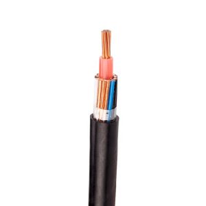 Aerial SNE CNE Airdac Cable
Aerial SNE CNE Cable is used for house connections, Used as a house service cable. Split concentric cable suitable for power distribution as an underground or overhead cable.
Aerial SNE CNE Airdac Cable
Aerial SNE CNE Cable is used for house connections, Used as a house service cable. Split concentric cable suitable for power distribution as an underground or overhead cable.
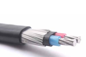 SERVICE ENTRANCE CONCENTRIC CABLE-DOMINICAN
The concentric cables are used as electric service entrance from the power distribution network until the meter panel (especially where it is required to prevent “black” losses or electric power robbery), and as feeder cable from the meters panel until the panel or general distribution panel, just…
SERVICE ENTRANCE CONCENTRIC CABLE-DOMINICAN
The concentric cables are used as electric service entrance from the power distribution network until the meter panel (especially where it is required to prevent “black” losses or electric power robbery), and as feeder cable from the meters panel until the panel or general distribution panel, just…
Related solutions
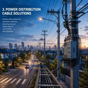
Power Distribution Cable Solutions
Qingzhou Cable provides low- and medium-voltage cable solutions for electrical distribution networks, supporting power delivery from substations to commercial, industrial and residential users.
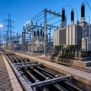
Power Substation Cable Solutions
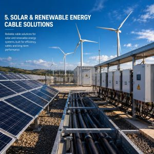
Solar & Renewable Energy Cable Solutions
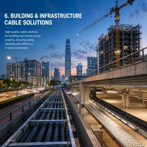
Building & Infrastructure Cable Solutions
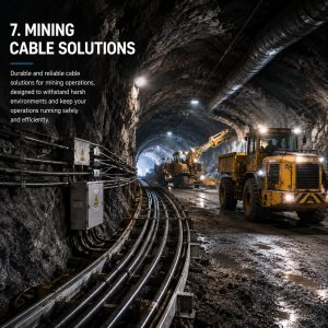
Mining Cable Solutions